歯車っぽい設定アイコン画像をつくる / 円周上の点を計算して図形を描画
![]()
歯車風の見た目の 設定アイコン をSVGで描画しようとおもった。 歯車の図形は円周上の点を計算してそれをつなぐとうまく描画できそうなので、 円周上の点の計算とそれらを組み合わせて図形をSVG描画する方法についてコードをまとめておきます。
原点を中心にした半径 r の円であれば、X軸との間の角度 Θ の円周上の点は ( r*cosΘ, r*sinΘ ) になる。ポイントはこれだけです。
では これを Groovy で実装して、SVGで描画していきましょう。
45度の位置にある円周上の点を計算
ラフイメージ
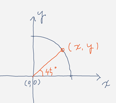
まずは、小手調べとして 半径12 で 45度の角度の点を計算してみる。
def toRadian = { degree-> degree * Math.PI/180f }

def r = 12
def degree = 45
def radian1 = toRadian(degree)
def x = Math.cos( radian1 ) * r
def y = Math.sin( radian1 ) * r

println "($x,$y)"
Math.cos(), Math.sin() に与える値の単位がラジアンなので、角度をラジアンに変換する必要がある点には注意。
Math.toRadians(角度) という関数が標準の java.lang.Math にあったわ.
0,45,90度の位置にある円周上の点を計算
ラフイメージ
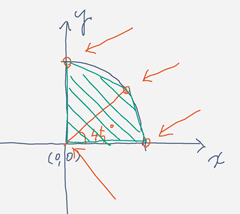
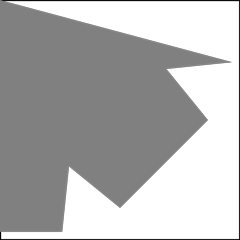
次に0,45,90度の位置にある円周上の3点を計算して、それと原点を加えた図形をSVG描画までしてみる。
def toRadian = { degree-> degree * Math.PI/180f }
def createPt = { x,y-> [x:x,y:y] }

// create points
def r = 12
def degreeList = [0, 45, 90]
def ptList = degreeList.collect { degree->
    def radian1 = toRadian(degree)
    def x = Math.cos( radian1 ) * r
    def y = Math.sin( radian1 ) * r
    createPt(x,y)
}

def ptO = createPt(0, 0)
ptList.add(ptO)

// create SVG commands
def svgCommandList = ["M ${ptO.x},${ptO.y}"] + ptList.collect{ pt-> "L ${pt.x},${pt.y}" }
svgCommandList << 'z'
def svgCommands = svgCommandList.join(' ')

// create SVG
def sb = new StringBuilder()
sb << '<svg xmlns="http://www.w3.org/2000/svg" width="400" height="400" viewBox="0 0 12 12">'
sb << '<path stroke="black" stroke-width=".1" fill="none" d="M 0,0 L 0,12 L 12,12 L 12,0 z"/>'
sb << '<path stroke="none" stroke-width=".1" fill="gray" d="'+svgCommands+'"/>'
sb << '</svg>'

new File('result.svg').text = sb.toString()
結果はこれ:
コンピュータの場合、手書きしたイメージ図とはY座標の方向が逆、 つまり、原点が左上にあって、Y座標が画面の下にいくにしたがって大きくなる。 そのため、SVGで書き出された図形は上下が反転した形になる。
そのへんの調整はプログラム側で transform すれば簡単に解決できるが今は重要な点ではないので、放置。
任意の円周上の点が計算できるようになったので、設定アイコンの1/4図形をつくる
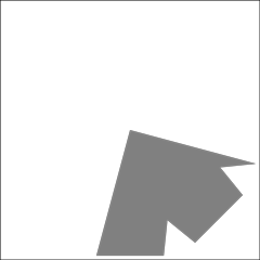
それでは当初の目的である設定アイコンの 右上(というか右下)1/4 部分をつくってみます。
ラフイメージ
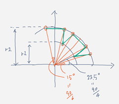
r1, r2の半径を持つ2つの円を想定。
- 内側は 22.5度と (90-22.5)度の位置にある円周上の点を計算
- 外側は 15度, 30度, 60度, 75度の位置にある円周上の点を計算
- 更に第一象限から出てしまいますが、第二象限にある (90+15)度 の位置にある点を計算
以上を考慮したコード:
def toRadian = { degree-> degree * Math.PI/180f }
def createPt = { x,y-> [x:x,y:y] }


// create points

// 円の半径と角度を与えて円周上の点を計算して返すクロージャ.
def pointFactory = { r, degree->
    def radian1 = toRadian(degree)
    def x = Math.cos( radian1 ) * r
    def y = Math.sin( radian1 ) * r
    createPt(x,y)
}

// 内側の円
def r1 = 9
def degreeList1    = [22.5, (90.0-22.5)]
def ptListOfInner  = degreeList1.collect( pointFactory.curry(r1) )

// 外側の円
def r2 = 12
def degreeList2     = [15, 30, 60, 75, (90+15)]
def ptListOfOuter  = degreeList2.collect( pointFactory.curry(r2) )

// 内側と外側の円上の点を描画したい順に並べ替えたリストをつくる
def pt0 = ptListOfOuter[0]
def pt1 = ptListOfInner[0]
def pt2 = ptListOfOuter[1]
def pt3 = ptListOfOuter[2]
def pt4 = ptListOfInner[1]
def pt5 = ptListOfOuter[3]
def pt6 = ptListOfOuter[4]

def ptList = [pt0, pt1, pt2, pt3, pt4, pt5, pt6]

// 原点
def ptO = createPt(0, 0)

// create SVG commands
def svgCommandList = ["M ${ptO.x},${ptO.y}"] + ptList.collect{ pt-> "L ${pt.x},${pt.y}" }
svgCommandList << 'z'
def svgCommands = svgCommandList.join(' ')


// create SVG
def sb = new StringBuilder()

sb << '<svg xmlns="http://www.w3.org/2000/svg" width="400" height="400" viewBox="0 0 12 12">'
sb << '<path stroke="black" stroke-width=".1" fill="none" d="M 0,0 L 0,12 L 12,12 L 12,0 z"/>'
sb << '<path stroke="none" stroke-width=".1" fill="gray" d="'+svgCommands+'"/>'
sb << '</svg>'

new File('result.svg').text = sb.toString()
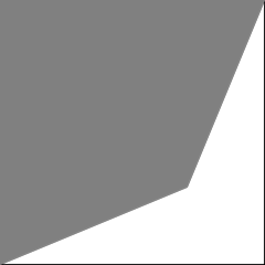
結果はこれ:
第二象限部分が画面外になっているので 見えません。 x 方向, y 方向に 12 だけ並行移動して、描画位置を調整して、全体を見渡せるようにした結果がこれ:
いよいよ設定アイコンをつくる
第一象限の 0..90度のあたりの範囲の設定アイコン図形は描画できたので、あとは、これを 0..360度あたりまで 4倍に拡張するだけです。
def toRadian = { degree-> degree * Math.PI/180f }
def createPt = { x,y-> [x:x,y:y] }


// create points

// 円の半径と角度を与えて円周上の点を計算して返すクロージャ.
def pointFactory = { r, degree->
    def radian1 = toRadian(degree)
    def x = Math.cos( radian1 ) * r
    def y = Math.sin( radian1 ) * r
    createPt(x,y)
}

// 内側の円
def r1 = 9
def degreeList1    = [22.5, (90.0-22.5)]
def ptListOfInner1  = degreeList1.collect( pointFactory.curry(r1) )
def ptListOfInner2  = degreeList1.collect { it+90*1 } .collect( pointFactory.curry(r1) )
def ptListOfInner3  = degreeList1.collect { it+90*2 } .collect( pointFactory.curry(r1) )
def ptListOfInner4  = degreeList1.collect { it+90*3 } .collect( pointFactory.curry(r1) )

// 外側の円
def r2 = 12
def degreeList2     = [15, 30, 60, 75, (90+15)]
def ptListOfOuter1  = degreeList2.collect( pointFactory.curry(r2) )
def ptListOfOuter2  = degreeList2.collect { it+90*1 } .collect( pointFactory.curry(r2) )
def ptListOfOuter3  = degreeList2.collect { it+90*2 } .collect( pointFactory.curry(r2) )
def ptListOfOuter4  = degreeList2.collect { it+90*3 } .collect( pointFactory.curry(r2) )


// 内側と外側の円上の点を描画したい順に並べ替えたリストをつくる
def createPtList = { ptListOfInner, ptListOfOuter->
    def pt0 = ptListOfOuter[0]
    def pt1 = ptListOfInner[0]
    def pt2 = ptListOfOuter[1]
    def pt3 = ptListOfOuter[2]
    def pt4 = ptListOfInner[1]
    def pt5 = ptListOfOuter[3]
    def pt6 = ptListOfOuter[4]

    [pt0, pt1, pt2, pt3, pt4, pt5, pt6]
}

def ptO = createPt(0, 0) // 原点

def ptList =
    [ptO] +
    createPtList(ptListOfInner1, ptListOfOuter1) +
    createPtList(ptListOfInner2, ptListOfOuter2) +
    createPtList(ptListOfInner3, ptListOfOuter3) +
    createPtList(ptListOfInner4, ptListOfOuter4)

def translate = { pt, tx, ty-> createPt(pt.x +tx, pt.y +ty) }
def fixedPtList = ptList.collect { translate(it, 12,12) }

// create SVG commands
def svgCommandList = ["M ${fixedPtList.head().x},${fixedPtList.head().y}"] + fixedPtList.tail().collect{ pt-> "L ${pt.x},${pt.y}" }
svgCommandList << 'z'
def svgCommands = svgCommandList.join(' ')


// create SVG
def sb = new StringBuilder()

sb << '<svg xmlns="http://www.w3.org/2000/svg" width="400" height="400" viewBox="0 0 24 24">'
sb << '<path stroke="black" stroke-width=".1" fill="none" d="M 0,0 L 0,24 L 24,24 L 24,0 z"/>'
sb << '<path stroke="none" stroke-width=".1" fill="gray" d="'+svgCommands+'"/>'
sb << '</svg>'

new File('result.svg').text = sb.toString()
結果はこれ:
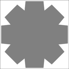
なんとなく、できました。 真ん中をくり抜かないと歯車感が出ない気がしますね。
もう少し歯車っぽく改良する
ポイントは
- (1)真ん中をくり抜く
- (2)外側の突起をもっと細くする
の2点です。 これを実現するために、コードにいろいろ手を加えました。
def toRadian = { degree-> degree * Math.PI/180f }
def createPt = { x,y-> [x:x,y:y] }


// create points

// 円の半径と角度を与えて円周上の点を計算して返すクロージャ.
def pointFactory = { r, degree->
    def radian1 = toRadian(degree)
    def x = Math.cos( radian1 ) * r
    def y = Math.sin( radian1 ) * r
    createPt(x,y)
}

// 歯車の内側の円
def r0 = 5
def degreeList0    = [22.5, (90.0-22.5)]
def ptListOfMoreInner1  = degreeList0.collect( pointFactory.curry(r0) )
def ptListOfMoreInner2  = degreeList0.collect { it+90*1 } .collect( pointFactory.curry(r0) )
def ptListOfMoreInner3  = degreeList0.collect { it+90*2 } .collect( pointFactory.curry(r0) )
def ptListOfMoreInner4  = degreeList0.collect { it+90*3 } .collect( pointFactory.curry(r0) )

// 内側の円
def r1 = 7.5
def degreeList1    = [22.5, (90.0-22.5)]
def ptListOfInner1  = degreeList1.collect( pointFactory.curry(r1) )
def ptListOfInner2  = degreeList1.collect { it+90*1 } .collect( pointFactory.curry(r1) )
def ptListOfInner3  = degreeList1.collect { it+90*2 } .collect( pointFactory.curry(r1) )
def ptListOfInner4  = degreeList1.collect { it+90*3 } .collect( pointFactory.curry(r1) )

// 外側の円
def r2 = 11.5
//def degreeList2     = [15, 30, 60, 75, (90+15)]
int magickValue = 7
def degreeList2     = [(15-magickValue), (30+magickValue), (60-magickValue), 75+magickValue, (90+15-magickValue)]
def ptListOfOuter1  = degreeList2.collect( pointFactory.curry(r2) )
def ptListOfOuter2  = degreeList2.collect { it+90*1 } .collect( pointFactory.curry(r2) )
def ptListOfOuter3  = degreeList2.collect { it+90*2 } .collect( pointFactory.curry(r2) )
def ptListOfOuter4  = degreeList2.collect { it+90*3 } .collect( pointFactory.curry(r2) )


// 内側と外側の円上の点を描画したい順に並べ替えたリストをつくる
def createPtList = { ptListOfInner, ptListOfOuter->
    def pt0 = ptListOfOuter[0]
    def pt1 = ptListOfInner[0]
    def pt2 = ptListOfOuter[1]
    def pt3 = ptListOfOuter[2]
    def pt4 = ptListOfInner[1]
    def pt5 = ptListOfOuter[3]
    def pt6 = ptListOfOuter[4]

    [pt0, pt1, pt2, pt3, pt4, pt5, pt6]
}

//def ptO = createPt(0, 0) // 原点

def ptList0 =
    createPtList(ptListOfInner1, ptListOfOuter1) +
    createPtList(ptListOfInner2, ptListOfOuter2) +
    createPtList(ptListOfInner3, ptListOfOuter3) +
    createPtList(ptListOfInner4, ptListOfOuter4)

def ptList =
    ptList0.drop(1) +
    [ptList0[1]] +
    [
        ptListOfMoreInner1[0], ptListOfMoreInner1[1],
        ptListOfMoreInner2[0], ptListOfMoreInner2[1],
        ptListOfMoreInner3[0], ptListOfMoreInner3[1],
        ptListOfMoreInner4[0], ptListOfMoreInner4[1],
        ptListOfMoreInner1[0]
        ].reverse()


def translate = { pt, tx, ty-> createPt(pt.x +tx, pt.y +ty) }
def fixedPtList = ptList.collect { translate(it, 12,12) }

// create SVG commands
def svgCommandList = ["M ${fixedPtList.head().x},${fixedPtList.head().y}"] + fixedPtList.tail().collect{ pt-> "L ${pt.x},${pt.y}" }
svgCommandList << 'z'
def svgCommands = svgCommandList.join(' ')


// create SVG
def sb = new StringBuilder()

sb << '<svg xmlns="http://www.w3.org/2000/svg" width="400" height="400" viewBox="0 0 24 24">'
sb << '<path stroke="black" stroke-width=".1" fill="none" d="M 0,0 L 0,24 L 24,24 L 24,0 z"/>'
sb << '<path stroke="none" stroke-width=".1" fill="gray" d="'+svgCommands+'"/>'
sb << '</svg>'

new File('result.svg').text = sb.toString()
結果はこれ:
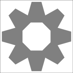
かなり歯車っぽさが増しました。
まとめ
歯車なので、2つの歯車を脳内で並べたときにそれぞれの突起が噛み合うように それらが十分細くないといけない ということがわかりました。